Monday, October 03, 2022

Solar Plane continued...

 A solar plane with multiple rows on the wings will have differnt illumination on each row and on each wing. The last plane had 3 rows x 2 wings. So 6 total channels of power point tracking.

I think the new design is going to be slightly smaller with two rows.  The 12 or 13 cells in series will have a max output voltage of ~7.5V.  So my system battery/bus voltage will need to be above that.
I'm thinking 6S LiIon.

So I wanted to simulate the power circuitry of the solar mppt system.
I used the LTC Spice and built a singe solar cell model:


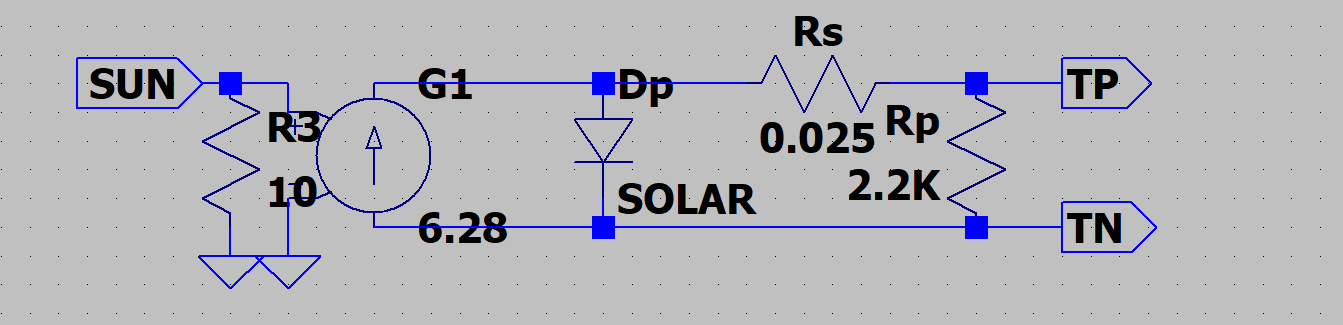
I then combined 10 of these to be a 10 cell array....


Then I used the LTC7804 test jig as the basis for a full up simulation.


So instead of regulating the output voltage it now regulates the input voltage.
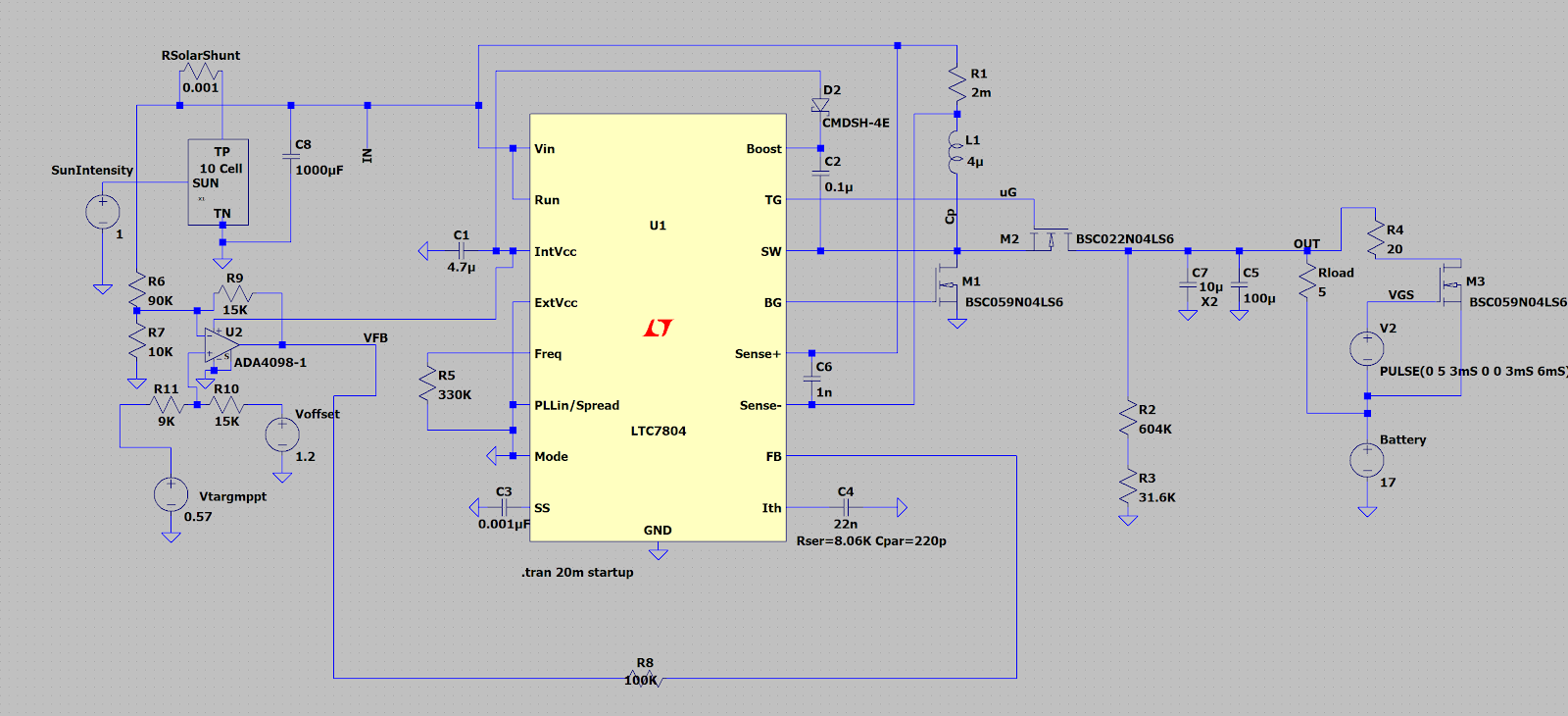
The op amp on the left side inverts, amplifies and offsets the cell array voltage and adapts it to the LTC7804 1.2V reference.

The two voltage sources on the left side Vtargmppt and Voffset will be combined into a low power precision DAC from whatever microcontroller I choose to drive this mess. (One could thevenize the resistance and voltages to form a single source, but since no significant current should flow into the
+ node of the op amp the resistance probably does not really matter.
Basic power path is decided, now to make a couple more decisions and prototype in the real world with a set of real cells.

For deciding the MPPT tracking point there are several choices:
Random path search.
Percentage of Voc (what I chose last time)
Table of V vs Cell temp.

I'll play with all three modes... I'm hoping the cell temp vs V works well.
The data sheet says Vmppt is  5.8V at 25C and is -1.84 mv/deg C.

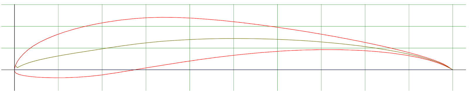
On the airframe front I've also been playing with basic aircraft layout using
XFLR5 to design the airframe.  While a solar wing really wants to be rectangular the
improvement in minimum sink with an additional tapered panel is so large that its probably worth doing even if it has no solar cells. (Winglets have same effect, but shadow top side cells so that does not work.) 

I really need to get a good target weight I'm comfortable with so I can have a target design and then determine gram/watt sort of sensitivities to make proper power/weight trades.
an example trade would be to add cells to the tailboom. Hard to balance as all the weight is aft and 
so will likely need added wt forward. The weight and drag acts 24 hrs a day. Added power is only useful for 12hrs and then requires added battery wt to use the excess power overnight.

Adding panels in the taper tips are at differnt angle/solar incidence than the main wing cells.
So they need their own mppt tracker. does it make sense to add a tracker for 15W of cell
running at 1.5 to 2 V so efficiency will be poor. With the LTC7408 it has synchronous reftification so that should help at low voltages.  (Inductor will be smaller as well).

Speaking of inductors I've gotten proper aluminum magnet wire quoted at $2.20/ft and 1Kft minimum order.  So I've 3d printed some air core toroid forms and wound un insulated aluminum craft wire on these...made some light inductors....        

Trades/Trades/optimizations as far as the eye can see... More later.


Saturday, September 17, 2022

Solar powered planes.


 In 2004 I built a solar powered RC plane.
You can see pictures and read about it sees some pictures and relive its sad end here: Old web page from 2004

I'm going to try this project again.

In the 18 years since this flew a number of things have improved:

  • Microscopic autopilots for RC planes are COTS. (mRo <5gm  etc)  I  no longer have to build my own.
  • Long range RC control and telemetry links are COTS (Crossfire, ELRS, Dragonlink)
    I no longer have to build my own.
  • The solar cells have improved. The new SunPower C60 cells are 6.5 gm 3.5W 22% efficient and Flexible. The A-300 cells I used 18 yrs ago were:12 gm, 3W 20% efficient, and pretty rigid.

Old cell left, new cell right

The new cells are pretty flexible.


On the old plane I had 3 rows of solar cells on each wing. Each row was wired in series to make about 6.5 volts. I then built a 6 channel MPPT (see: wiki MPPT)

The schematic for one channel of my MPPT:

The full 6 channel unit:


This MPPT is setup as a boost converter so the system bus or battery voltage must be above the voltage of the solar string. It also allows solar strings of varying size to feed a common bus. IE I can have a 4 cell panel on the tail, a 4 cell panel on the wing tips and a 2x 10 cell panels on each main wing.

There are lots and lots of interesting tradeoffs in this space.
At minimum power the wing drag is primarily induced drag. One reduces induced drag by making the wing have a very high aspect ratio and an  elliptical lift distribution.

If you want the absolute minimum power you want a  really high lift airfoil like:
S1210:


Selig S1210

Yet look how thin the trailing edge is and how hard that would be to build lightly.
Heavily under cambered airfoils also have really high pitching moments.
(Meaning the airfoil wants to pitch forward and this must be resisted.)
Put this airfoil on a really long high aspect ratio wing and its not unheard of for the wing tip to fail in a downward direction... (The airfoil tip tries to twist forward twisting the wing, enough that the wing tip on light structure is now lifting down and bad things ensue.)

One could choose an airfoil designed for flying wings (now or very low pitching moment) like 
MH60:

Much easier to build a very light structure with this trailing edge and the torsional rigidity of the wing will matter a lot less.


The minimum power airfoil (assuming an infinite wing) is  where Cl^3/2/Cd is maximum.
For the  1210 :  109 For the MH60 its : 68....

So the minimum sink is roughly proportional  to weight ^ 1/2  Min power is thus weight ^(3/2)
So for a 1000gm airplane you could add a couple hundred extra grams and be even.

So if one wanted to fly over night.... using the potential energy of the aircraft as a battery  sink rate is only effected by wt ^1/2 where if you wanted to fly all night  at constant altitude via battery then assuming the battery is 30 to 50%  of the mass (reasonable assumption) then each extra gram of structure is bad by an additional requirement for more battery.

Like I said a really complex trade space...


Looking at the professional Aerospace for hints/clues is not really helpful...
Helios was a flying wing, that failed due to complex aerodynamic, structural, and turbulence interactions. See Report here

The Solar impulse and Airbus Zypher both chose a more traditional aircraft platform.


Friday, February 22, 2019

Creating new things in the real world, Musk, Tesla Spacex etc....

I'm a space geek, much of my social interaction is with other space geeks.
A lot of these people worship what Spacex and Elon have accomplished.

At the same time I've been more and more convinced that Tesla is going to fail.
This causes some significant personal cognitive dissonance.

The following is my attempt to work this out ...

Making a new thing is hard. You will fail, over and over again, you will fail.
Edison tried thousands of light bulb filaments before he found one that worked.

One of the really cool things about spacex is that they let you see them fail.
The blooper reel of landing attempts is outstanding.
Attempting to do something new and hard will have failures.
Trying something new in engineering or in business will have failures.

Because of Spacex:
  • We now know that first stage reuse can make sense.
  • We now know that the iterate fast model of engineering works for at least some of the  aerospace world.
  • Supersonic retro propulsion works.
  • You can (given the right engineering team ) built rockets for a tiny fraction of what the big aerospace primes charge.
All of this is new information in the world due to Spacex efforts.
Everything above this line is engineering....

We still don't really  know that the Spacex way will work in a business sense.
Recent layoffs and recent failed funding raise make this more questionable than it was 12 months ago. (Its clear that  the business case for the large aerospace primes, does not  work absent billions in direct government subsidies)

From an engineering stand point Spacex has been somewhat innovative....
SpaceX  have either surpassed or are approaching 50% of the total world wide launches.
In my opinion (if ancillary things like tesla don't take it out) Spacex will survive long term and the world will be a better place because of that. (see my earlier dialog on why space matters).

The space business has been run for a long time by cost plus contractors working for governments.
This is not a place where innovation thrives.

The Car business on the other had has been a brutally competitive market with microscopic  margins fought over by  efficient international behemoths. Its a hard brutal world.

Tesla managed to crack open that market and with the S and X, they  delivered  a well received  high end quality product that changed the perception of the world. Now every one of those behemoths is planning an EV. Just having a shot at this is a huge achievement...

Some how the engineer Elon that allows us to see spacex failures, has been unable to admit to the world that their are also business failures. By any unbiased measure Solar City was weeks from failing when Tesla bought it.  This burdens Tesla with a millstone that makes the difficult task of breaking into the brutally competitive car market even harder.

Watching the Engineer Elon do magic things at spacex I greatly admire  what he/they have accomplished.   Watching the Business Man Elon commit what looks very much like Fraud to save a failing business I do not admire.  Business ethics matter and used to matter to Elon (see his several year old  tweet about debts and personal responsibility for Solar City Debits) 

Some how the pressure to not have the business fail has pushed pushed Elon to do things that cross the ethical line in a way that has caused me to loose my respect for Business Man Elon...

The Big ones :
  • Solar City Purchase and fraudulent Solar roof presentation.
  • Model 3 production guarantees on the eve of big Tesla Bond Raise.
  • Screwing over his devoted customer base with the crappy quality M3 and things like not refunding deposits.
  • The $420 Funding secured Tweet and subsequent response.
  • The flipping the Bird at the SEC taunting tweets.
  • The recent guidance on Tesla that just does not pass the smell test.
  • The Fraudulent Guarantees in the Buffalo Solar city Factory morass.
  • Treatment of personnel (At both Spacex and Tesla) You can only run in start up panic mode for so long before it destroys people. I have many space friends that have left Spacex because of the relentless pressure.
It is my opinion that Tesla is very close to failing and will fail in the next 24 months.
It is my hope that this does not destroy Spacex. Elon has generated significant personal liabilities in his Tesla dealings, and if Tesla fails the only real Asset Elons owns is spacex. Spacex will be a very different and less dynamic place when its owned by plaintive s lawyers rather than Elon.

I find the whole affair sad.  I wish Elon had stuck to Spacex and just focused there.

I know that some of my followers that see the Spacex brilliance  and subscribe toe the "Saint Elon can do anything" view will rush in to defend Tesla.
I don't want to rehash that argument here. lets us just agree to disagree and we will know who is correct in 18 months or so.


Saturday, December 22, 2018

Low Low Low cost liquid thrust chambers...


The very premise of what I’m trying to do is low cost as a primary design goal.
One has to question ALL of ones assumptions…
I personally fired the first ever 3D printed Regenerativly cooled liquid rocket engine.
ever fired in the world (2009)
I’ve done a lot of work in that space. The 3D aluminum costs are coming down….
Its cool high tech and in many ways awesome. Its also the single most expensive hardware component on my rocket by a factor of 3. For the long term business case to work I need to get the single 6” 24 foot tube cost ready to fly under $2K.  A die cast aluminum inner with a saddle jacket outer made from injection molded saddle and thin wall extruded aluminum outer is a rocket motor with a cost of under $200.00   So for the next generation of motors I’m going to abandon the 3D printed motors…
The first rocket motor I designed my self, and the 2nd liquid rocket motor I ever fired was saddle jacket, and  this generation will be as well. (113 Sec Fireing) 

 I’ll use machined aluminum done on my CNC lathe /mill as a stand in for di-cast aluminum. And the Saddle will either be machined aluminum or possibly machined polyethylene as a stand in for injection molded. 


Saturday, December 15, 2018

Fusion360 cad beg...

I'm tryingto convert from Rhino to fusion 360.

The following was done in rhino, I'm trying to learn how to do the same in fusion...

I can easily draw this in fusion a Extruded cylinder with a hole in it.

I Can also draw my o-ring groove in fusion....


In Rhino I next draw two spheres.....(Blue and green)


Then I generate the line where the spheres intersect the cylinder.
(Inner intersection lines have been removed for clarity)
(I did this twice and the blue/green colors swapped  sorry for the confusion)


I then use the sweep2 command in Rhino to make a solid from o-ring profile and the two "Rails"
This is correctly tangent to the cylinder surface and has the correct o-ring breaks, radis etc...


Then subtract the solid and I have my o-ring grove.

So my fundamental fusion 360 issues....
I can't draw the spheres based on points, only dimensions. The lower dimension is easy to derive its the hole radius +the oring offset. The outer sphere is a lot harder as the oring groove sides are not straight and while I can place a point in the appropriate place fusion won't let me draw a sphere to the point. That problem I could work around with some triganometry, but the 2nd problem I can't seem to solve. I need to create a pair of lines to sweep the pattern, these lines need to be the intersection of a sphere and the cylinder. I can't seem to create this geometry no matter how I try.

Advice welcome.


Monday, November 19, 2018

0.018" matters...

I had a batch of end caps machined for the Carbon tube tank.
This was 4" outer, 0.035 metal liner 0.009  poly bag, and 0.004 gap.
This was all carefully measured and tested, it works well...

I thought I could reuse these end caps in the 4" 035 wall tube, alas I neglected to account for the bag.
The 0.009 on both sides or 0.0018 in diameter is enough that the caps don't seal correctly.....
Grumble Grumble....
I could line the aluminum tube with the bag and continue....


Not a huge deal, but I thought I had enough for 3 sets of flight hardware, now I have zero...
I need to machine new ones...

So even with the loose fit, I thought I'd assemble the tank and  hydro test one.
The end cap retention failed at 420PSI. The cap retaining screws failed in shear.
In hind sight I did not use enough screws, according to the screw stress calculations they should have failed at 390 psi.


So all in all its nice to actually be building and assembling hardware again.

So Mariellen's garden got its first dose of hydro test water, in about 4 years.

Wednesday morning update...
Rebuilt the test tank, used more screws, hydro ed
to 600 PSI without failure.


Thursday, November 15, 2018

Fill Drain how to make safe...

One way to fill a tank... (and how I've filled every rocket tank to date)
Is just put a removable fitting on the top of the tank and pour in the propellant.
Its real hard to make a system lighter than just a single AN cap.

This has several problems...
  • It does not scale, in a Otrag vehilce you might have 128+ tanks to fill.
  • On a biprop vehicle, once one of the propellants is loaded loading the other propellant becomes a hazard.
  • Its very difficult to precisely fill to exact levels.
  • It does not help you drain after an abort scenario.

    So I'd like to do remote fill and drain on the vehicle without adding a bunch of weight...
    Here is one possible scheme that can be done with a single tank penetration.


At the expense of wasign some propellant it ensures the system is filled to a precise level (the level of the bottom of the dip tube, and only requires one tank penetration.

It has the added advaltage that if you use the valve RV1 to vent the tank in an in flight abort, it does nto vent the all the propellant, only the pressurization gas.... With Lox its not an issue to dump propellant while in the air, with H2O2 dumping in the air can start a large area brush fire.